
Vibrating screen mesh blinding occurs when apertures lose effective open area because wet fines coat the surface, near-size particles lodge in openings, or compacted material covers part of the deck. Diagnose the blockage pattern first, then check material moisture and clay, feed gradation, bed depth, distribution, screen-media condition, tension and machine motion before selecting a corrective action.

First Separate Blinding, Pegging and Bed Cover
Operators often use “blinding” for any reduction in visible open area, but the physical mechanism matters. Wet blinding forms when moisture, clay or fine particles create an adhering layer across or within the openings. Pegging occurs when particles close to the aperture size or with an unfavorable shape wedge into individual holes. A third condition appears when an overly deep or poorly distributed bed simply prevents enough particles from reaching the deck.
These faults can occur together. For example, a wet feed may form cohesive clusters while a high feed rate keeps the deck covered. Photograph the blocked area before cleaning, note where it begins and compare the feed end, middle and discharge end. That evidence is more useful than a general statement that the vibrating screen has lost capacity.
Vibrating Screen Mesh Blinding Symptoms and Likely Causes
| Observed Pattern | Likely Mechanism | Evidence to Collect | Corrective Direction |
|---|---|---|---|
| Sticky film across many apertures | Moist fines, clay, surface water or cohesive feed coating the screen media. | Moisture and clay condition, weather, spray-water changes, buildup texture and location. | Address the moisture or feed-preparation cause; review media intended for sticky material. |
| Individual particles wedged in openings | Near-aperture particles, elongated fragments or an aperture shape that promotes lodging. | Size and shape of lodged particles, feed gradation, aperture dimensions and wear. | Confirm cut-size requirements, media geometry and particle-shape behavior before changing panels. |
| Blockage concentrated at the feed end | High impact, excessive local bed depth, off-center feed or insufficient initial distribution. | Chute trajectory, feed width, bed-depth profile and feeder discharge pattern. | Improve controlled distribution and remove avoidable point loading. |
| Open area falls during wet periods | Changed surface moisture, clay behavior or agglomeration after rain or washing changes. | Stable-period versus fault-period material samples and operating records. | Treat the material-condition change rather than assuming a permanent machine fault. |
| One side blinds faster than the other | Uneven feed distribution, deck level, localized spray, panel tension or support condition. | Side-to-side bed depth, chute alignment, panel installation and support inspection. | Correct the asymmetry before increasing machine settings. |
| Blockage returns soon after cleaning | The underlying feed, media, loading or motion mismatch remains unresolved. | Time to recurrence, location, operating state and material condition after restart. | Compare the recurrence pattern with the process baseline and test one approved correction. |
1. Wet Fines and Clay Can Coat the Openings
External moisture can create liquid bridges between fine particles, while clay can increase cohesion and adhesion. As a result, fines combine into clusters or form a film on the deck. The effective aperture then becomes smaller even though the nominal opening has not changed.
Compare representative samples from a stable period and the fault period. Record surface moisture, clay behavior, fines content, recent rain, washing changes and stockpile drainage. A wet-looking feed is not enough evidence by itself; the important question is whether the material adheres, agglomerates and repeatedly closes openings under the current duty.
Cleaning may temporarily recover open area, but recurrence shows that the source condition remains. Depending on the verified process, the durable response may involve upstream drainage, controlled feed blending, revised washing practice, improved distribution or screen media selected for sticky fines. Any change still has to meet the required cut size and product specification.
2. Near-Size and Elongated Particles Can Peg the Mesh
Particles slightly larger than an opening may enter far enough to wedge without passing. Elongated or flat fragments can behave differently from rounded particles with the same nominal size. Consequently, two feeds with similar size distributions can create different pegging patterns.
Remove a representative set of lodged particles only after the equipment is safely isolated. Measure their relevant dimensions and compare them with the actual worn aperture, not only the new-panel specification. Also examine whether pegging occurs across the full deck or mainly in one loading zone.
Possible corrections include reviewing aperture shape, orientation, media construction or the upstream crushing duty. However, a larger opening is not an automatic solution because it can change the finished product. The earlier guide to vibrating screen efficiency factors explains how aperture, feed distribution and operating variables interact beyond blockage alone.
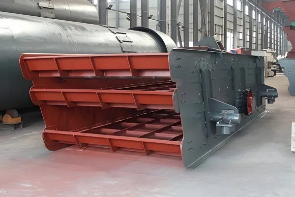
3. Bed Depth and Feed Distribution May Hide Available Open Area
Screening requires particles to stratify and approach an opening. When the bed is too deep, fine particles have fewer opportunities to reach the deck before the material leaves the machine. The screen may look covered and the undersize flow may fall even when many apertures remain physically open.
Measure bed depth at repeatable points across the width and along the deck. Compare the feed rate and size distribution with a stable baseline. If one side carries more material, inspect the inlet chute, gate, splitter, tray alignment and the discharge pattern from the upstream vibrating feeder.
Reducing feed without understanding the plant can move the problem elsewhere. Instead, determine whether the screen is overloaded, unevenly loaded or receiving a changed gradation. Review recirculating material as well, because a larger return load can increase near-size content and deck loading throughout a stationary crushing system.
4. Screen Media Must Match the Material and Separation Duty
Woven wire, perforated plate, rubber and polyurethane media do not present identical aperture geometry, flexibility or surface behavior. Aperture shape and orientation also affect how particles approach and pass through the deck. Therefore, media should be selected around the required cut, feed shape, impact, abrasion, moisture and maintenance conditions.
Inspect panel type, aperture dimensions, wear, deformation, damaged fastening points and any local loss of tension. A worn opening may pass oversize product, while a distorted or slack panel can alter particle movement and encourage material retention. Record the exact media identification before proposing a replacement.
Self-cleaning or more flexible media may help a verified pegging or sticky-material duty, but no media solves every case. The chosen surface must still provide structural compatibility, acceptable wear life, required product control and safe installation within the specific screen.
5. Verify Tension, Supports and Machine Motion
The deck, media, fastening system, cross members, springs, drive and support structure form one dynamic assembly. Loose or uneven tension can create dead areas. Damaged supports, material packed around structural clearances, loose fasteners or abnormal motion can also reduce the deck action needed to move and stratify material.
Follow the inspection and measurement procedure for the exact machine. Compare approved speed, stroke, direction, motor current or other available indicators with the established baseline. Do not copy a frequency, amplitude or inclination from another screen, because deck mass, support system, drive arrangement and process duty differ.
If blockage began after panel replacement, structural repair, added spray bars or another modification, verify installation and mass distribution before retuning the machine. A correction should restore the approved assembly condition or receive engineering review.

A Safe Corrective-Action Sequence
Observe normal operation only from protected locations. Before cleaning, removing lodged particles, touching panels or entering a screen area, isolate and verify all applicable electrical, mechanical, gravitational and stored energy under the site procedure. The official OSHA hazardous-energy guidance explains the need to prevent unexpected startup or energy release during service work; each facility must follow the laws and procedures that apply in its jurisdiction.
- Define the pattern. Record whether the deck shows wet coating, individual pegging, excessive bed cover or localized blockage.
- Locate the first change. Compare the feed end, deck center, discharge end and both sides of the machine.
- Record the operating context. Capture feed rate, gradation, moisture, clay condition, recirculating load, weather and recent plant changes.
- Make the equipment safe. Complete required isolation, verification, access and lifting controls before physical work.
- Inspect the material and media. Check lodged-particle dimensions, aperture condition, wear, panel tension, fastening and buildup.
- Inspect the screening system. Review feed distribution, bed depth, drive condition, supports, clearances and downstream restrictions.
- Select one approved correction. Address the verified mechanism without compromising product size or equipment limits.
- Measure recurrence. After restart, record open area, undersize flow, product sizing and time to any renewed blockage.
Corrections That Can Make the Problem Worse
Increasing vibration without evidence can raise structural and component loads while leaving a wet-material or feed-distribution problem unchanged. Opening the aperture may reduce pegging but allow unacceptable oversize into the product. Continuous manual cleaning addresses the symptom and can expose personnel to repeated maintenance hazards.
Likewise, adding unapproved balls, chains, impact devices or panel modifications can damage media and alter the dynamic system. Water sprays may help one wet-screening process but can worsen adhesion, create handling problems or conflict with a dry circuit. Each response should follow the material behavior, product requirement and approved equipment design.
Data Needed for a Reliable Screen Review
Provide the screen model, deck arrangement, motion type, installed media, aperture dimensions, installation angle, feed rate, full size distribution, bulk density, moisture and clay condition, required product sizes and upstream and downstream equipment. Add photographs of the blockage pattern before cleaning and after a controlled operating period.
Useful operating records include bed depth across the deck, feed distribution, available drive trends, recirculating load, screen product samples, recent media changes and time to recurrence. If the deck protects a mill from oversize feed, the article on screening before grinding provides additional circuit context.
Vibrating Screen Mesh Blinding FAQ
What is the difference between screen blinding and pegging?
Blinding commonly describes fines or sticky material coating and closing apertures. Pegging describes individual near-size or irregular particles wedged in openings. The mechanisms can occur together, but they require different evidence and corrective actions.
Why does a vibrating screen blind more after rain?
Rain can increase surface moisture and strengthen adhesion or agglomeration, especially when the feed contains fines or clay. Compare fault-period material with a stable baseline and inspect stockpile drainage, feed preparation and the location of the coating.
Can higher vibration clear blocked screen mesh?
Not reliably. It may not correct wet coating, excessive bed depth, poor distribution or unsuitable media, and it can increase machine loads. Verify the cause and remain within the approved settings for the exact screen.
When should screen media be changed?
Review a media change when evidence shows that aperture geometry, flexibility, wear behavior or surface action does not suit the confirmed material and separation duty. The replacement must remain compatible with the machine and required product size.
What should be measured after a corrective action?
Record the blockage pattern, effective open area, bed depth, feed distribution, undersize flow, product sizing and time to recurrence under comparable feed conditions. These measurements show whether the correction addressed the cause instead of only cleaning the symptom.