
A flotation cell maintenance inspection should connect mechanical condition with process evidence. Check the drive, shaft, rotor-stator mechanism, air delivery, pulp-level controls, launders, tank and instruments, then compare the findings with power, vibration, air flow, level stability and metallurgical trends. Froth appearance alone cannot prove that a cell is mechanically worn.

Why Mechanical and Process Checks Must Be Combined
A mechanical flotation cell must suspend solids, disperse air and provide a controlled pulp and froth environment. Those duties interact. A worn mechanism may alter air dispersion or mixing, but changes in particle size, pulp density, mineralogy, reagent condition or water chemistry can produce similar operating symptoms.
Begin with the operating context. Record the feed source, throughput, particle-size distribution, solids concentration and relevant reagent conditions when a symptom occurs. The guide to ore preparation before mineral separation explains why unstable feed can move through the flotation circuit even when the equipment itself is serviceable.
Online Checks Before a Planned Shutdown
Drive load and vibration
Trend motor current or power, gearbox condition and vibration against a stable operating baseline. A single high value is less useful than a repeated change under similar feed, air and level conditions.
Delivered air
Confirm actual flow or pressure at the cell or bank where instrumentation permits. Blower operation and valve position do not by themselves prove that the required air reaches the mechanism.
Pulp level and valve response
Compare the level signal, setpoint, actuator position and physical response. Oscillation may come from the sensor, valve sizing or condition, connected-cell interaction, feed disturbance or control tuning.
Froth distribution
Observe whether froth moves evenly toward the launders. Dead zones, surging or one-sided overflow are evidence to investigate, not a diagnosis by themselves.
Solids suspension
Look for signs of sanding, restricted transfer or abnormal density distribution using approved observation points and process measurements. Do not open or enter operating equipment.
Leakage and abnormal sound
Record seal leakage, air leaks, loose guards, rubbing or changing bearing and gearbox noise. Escalate sudden changes under the site’s operating and safety procedures.
Planned Shutdown Inspection Scope
| Area | What to Inspect | Evidence to Record | Why It Matters |
|---|---|---|---|
| Drive and support | Motor, coupling, gearbox, bearing housings, mounting points, shaft alignment and guards. | Vibration history, temperature history, leakage, looseness, alignment measurements and lubricant condition. | Drive condition affects mechanism speed, stability and availability. |
| Rotor and stator | Blade or vane wear, erosion pattern, cracks, deformation, fasteners and design clearances. | Repeatable dimensional measurements, photographs, component position and comparison with the approved limit. | Mechanism geometry influences mixing, solids suspension and air dispersion. |
| Air system | Piping, flexible connections, valves, manifolds, passages, filters and evidence of blockage or leakage. | Pressure and flow trends, valve position, leak location and cleaned obstruction material. | Uneven or restricted air delivery can appear as a flotation or mechanism problem. |
| Tank and flow path | Tank lining, baffles, inter-cell openings, dart valves, discharge passages and accumulated solids. | Wear location, buildup depth, corrosion or abrasion, valve travel and obstruction pattern. | Restrictions and wear alter residence, level and slurry distribution. |
| Launders and froth lip | Lip condition, levelness, buildup, blockages, supports and drainage. | Dimensions, damaged sections, uneven buildup and observed overflow pattern before shutdown. | Collection geometry affects how recovered froth leaves the cell. |
| Instrumentation | Air-flow, level, pressure, power and vibration instruments plus associated impulse lines and actuators. | Calibration result, response test, fouling, drift, signal quality and actuator stroke. | Control decisions are only as reliable as the measurement and final control element. |
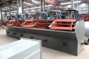
Interpret Symptoms With Confirming Evidence
| Observed Change | Possible Explanations | Checks That Help Confirm the Cause |
|---|---|---|
| Air flow falls | Restriction, leakage, valve or blower issue, instrument error, or mechanism wear in a self-aspirated cell. | Compare pressure and flow at several points, inspect air passages and verify the instrument before assigning the cause. |
| Power or vibration rises | Bearing or gearbox condition, looseness, misalignment, rubbing, solids accumulation or a change in slurry load. | Review trends under comparable process conditions and complete mechanical inspection and alignment checks. |
| Level oscillates | Feed surges, sensor fouling, sticky or worn valve, connected-cell interaction or unsuitable control response. | Compare level, valve position, feed flow and adjacent-cell trends; inspect the sensor and actuator. |
| Froth becomes uneven | Air distribution, level, launder condition, mechanism condition, feed or reagent change. | Check process chemistry and feed first, then map air, level and mechanical condition across the bank. |
| Cell sands or transfers poorly | Insufficient agitation, coarse or dense feed, restricted outlet, abnormal level or excessive solids loading. | Review grinding and classification data, pulp density, transfer openings, drive condition and mechanism measurements. |
| Recovery changes without a clear fault | Mineralogy, liberation, particle size, reagent condition, water quality, air or level variation. | Use representative sampling and metallurgical accounting before attributing the result to equipment wear. |
Use Baselines Instead of Generic Wear Percentages
Inspection becomes useful when measurements are repeatable. Mark measurement locations, use the same method at each shutdown and retain photographs with cell number, component position and date. Compare the result with the flotation machine documentation and the plant’s approved replacement criteria.
Do not apply a wear percentage from another mechanism as a universal limit. Rotor and stator geometry, duty, material, speed, air system and ore abrasiveness differ. The practical decision combines dimensional wear, damage mode, operating trends, remaining planned run time and the consequence of an in-service failure.
- cell and component identification;
- operating hours and previous replacement date;
- defined measurement points and method;
- air, level, power and vibration trends;
- feed size, solids and throughput at the time of the symptom;
- photographs that show location and scale;
- approved limit, finding, action and responsible owner;
- post-maintenance checks that confirm the expected response.
Check the Circuit Around the Cell
Flotation cells do not operate independently of the grinding and classification system. A shift in product size from the ball mill, cyclone performance or slurry density can change solids suspension, reagent demand and froth behavior. Likewise, an unstable upstream pump or conditioning stage can create symptoms that repeat across several cells.
Compare the affected cell with neighboring cells receiving similar feed. A bank-wide change points toward feed, air supply, water, reagents or control strategy; a cell-specific change makes local instrumentation, actuator, air passage or mechanism condition more likely. The overview of flotation and magnetic separation provides wider context for how separation methods depend on mineral properties and prepared feed.

Safety Boundary for Internal Inspection
The US Occupational Safety and Health Administration explains that servicing work can expose personnel to electrical, mechanical, hydraulic, pneumatic, chemical, thermal and other hazardous energy. Its control of hazardous energy overview describes the purpose of lockout/tagout programs and training. Apply the legal requirements and procedures relevant to the actual country and site.
Frequently Asked Questions
How often should a flotation cell be inspected?
Use a risk-based interval based on the manufacturer guidance, ore abrasiveness, operating hours, duty, condition trends and previous wear rate. Online checks can be frequent, while internal measurements require a planned and fully isolated shutdown.
Does unstable froth prove that the rotor or stator is worn?
No. Feed mineralogy, particle size, pulp density, reagents, water chemistry, air delivery and level control can all change froth behavior. Confirm the process conditions and inspect the mechanism before assigning the cause.
Which operating trends are most useful before shutdown?
Power or motor current, vibration, air flow or pressure, pulp level, valve position, feed rate, particle size, pulp density and metallurgical results provide a useful combined record when time-aligned.
Can one wear limit be used for every flotation cell?
No. Mechanism geometry, materials, speed, duty and manufacturer criteria differ. Use approved limits for the installed machine and compare repeatable measurements with the plant’s own wear history.
What information supports a flotation equipment review?
Provide ore and feed data, cell model and duty, throughput, operating hours, air and level arrangement, trend history, measured wear, failure pattern, available shutdown window and clear photographs of the affected components.
Vanore Mining supplies flotation equipment within broader mineral-processing equipment systems. For an equipment or circuit review, send the cell duty, feed properties, operating data and inspection findings through the Vanore Mining contact page.