
Vibrating feeder uneven feeding is usually traced by separating three different symptoms: flow that rises and falls over time, material concentrated on one side of the tray, or a hopper that releases batches after temporary blockage. Check hopper discharge, material moisture and size distribution, gate opening, tray loading, buildup, supports, fasteners, drive behavior and downstream demand in that order before changing vibration settings.

First Identify the Type of Uneven Feeding
A feeder can appear unstable for several unrelated reasons. Time-based fluctuation means the total discharge rate repeatedly increases and decreases. Side-to-side imbalance means the tray carries a deeper bed on one side. Surging means material stops or slows and then arrives as a batch. Each condition requires different evidence.
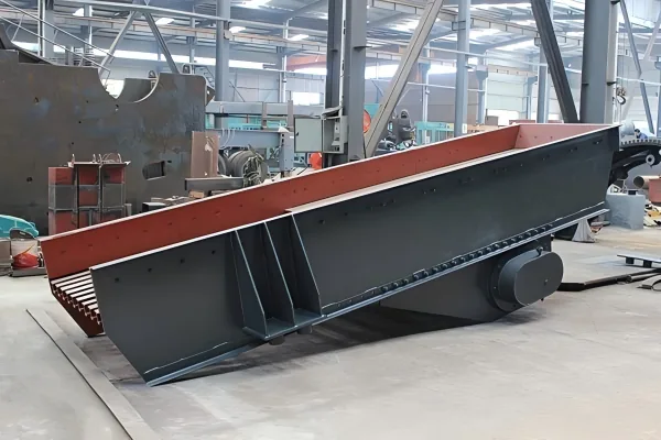
Observe the hopper outlet, receiving end, full tray width and discharge point at the same time where safe viewing positions allow. Compare those observations with downstream indicators such as crusher power, chamber level, conveyor loading or belt-scale trend. The Vanore vibrating feeder should be diagnosed as part of the material-handling path rather than as an isolated drive unit.
Vibrating Feeder Uneven Feeding Symptoms and Checks
| Observed Symptom | Likely Area to Investigate | Evidence to Collect | Avoid This Assumption |
|---|---|---|---|
| Flow repeatedly rises and falls | Hopper drawdown, bridging, upstream loading, control signal or intermittent downstream restriction. | Video of hopper and discharge, feeder command, belt loading and downstream operating trend on one timeline. | Do not assume that changing vibration intensity will remove a hopper-flow problem. |
| Material stays mostly on one side | Off-center hopper outlet, biased chute, uneven gate opening, tray level or asymmetric support condition. | Bed depth across the width, inlet trajectory, tray alignment and support measurements. | Do not judge total capacity from the heavily loaded side alone. |
| Material stops and releases in batches | Arching, ratholing, sticky fines, clay, frozen material or a restricted outlet. | Material condition, hopper wall buildup, outlet dimensions, drawdown pattern and weather changes. | Do not clear a blockage while equipment or stored energy remains uncontrolled. |
| Output falls gradually | Buildup, tray wear, changed material, loose fasteners, damaged springs, drive condition or added tray mass. | Clean versus loaded inspection, baseline displacement, component condition and material records. | Do not retune the feeder before checking for physical changes. |
| Feeder is stable but the crusher load fluctuates | Feed size segregation, crusher chamber behavior, recirculating load or another downstream constraint. | Feeder discharge mass, size distribution, crusher trend and return conveyor loading. | Do not call every downstream fluctuation a feeder-rate problem. |
| Noise or motion changes with load | Fasteners, springs, isolation elements, contact points, bearings, drive and supporting structure. | Manufacturer-approved inspections and measurements under empty and controlled load conditions. | Do not continue operation until abnormal mechanical contact has been assessed. |
1. Check Hopper Flow Before the Feeder Drive
The feeder can only regulate material that reaches its tray. A hopper may develop an arch above the outlet, a narrow flow channel through otherwise stagnant material, or cohesive buildup near the walls. These conditions can produce long pauses followed by sudden discharge even when feeder motion remains consistent.
Watch how the material surface draws down and whether the outlet remains covered consistently. Record changes in moisture, clay, fines and maximum lump size. If instability begins in the hopper, review storage geometry, outlet condition and the approved flow-assistance method rather than using greater feeder motion to force an uncertain blockage.
2. Compare Material Condition With the Baseline
Bulk solids do not flow according to one nominal rock type. Particle-size distribution, shape, moisture, clay content, bulk density and the proportion of fines affect how the bed moves and how readily the hopper discharges. A feeder that handled dry, graded stone steadily may behave differently after rain or when the quarry face changes.
Collect representative material information during the fault, not only after conditions return to normal. Compare feed gradation and moisture with an earlier stable period. Oversized lumps can interrupt the receiving zone, while sticky fines may adhere to the tray or form cohesive masses. The correction should address the verified material behavior and remain within the feeder’s approved feed envelope.
3. Inspect Gate Opening and Tray Loading
A gate that is not level or an inlet that does not cover the intended tray width can create persistent side loading. Excessive head pressure from the hopper may also change how material enters the tray. Inspect the opening, wear liners, chute edges and any buildup that narrows one side of the flow path.
Use repeatable marks or measurements across the tray to compare bed depth. If one side remains heavily loaded, correct the inlet distribution before adjusting the drive. Stable, centered delivery is especially important when the feeder supplies a jaw crusher, because uneven feed and large surges can disturb chamber loading and the upstream-to-downstream production rhythm.
4. Look for Buildup, Wear and Unapproved Modifications
Adhered material reduces usable tray volume and can add uneven mass. Worn liners or structural deformation can redirect flow. Added covers, liners, extensions or repairs may also change tray mass and stiffness, so a modification that appears minor can alter vibration behavior.
Compare the current assembly with drawings, previous photographs and the original operating baseline. Clean using the approved method, inspect wear distribution and document all alterations. Do not remove structural material, add weights or change the tray without engineering review for the exact feeder.

5. Verify Supports, Fasteners and Drive Condition
The tray, springs or isolation elements, drive and support frame form one dynamic system. Loose fasteners, damaged springs, foreign material trapped around supports, bearing problems or contact with adjacent steelwork can change motion and create noise. A distorted foundation or unequal support elevation can also bias the tray.
Follow the manufacturer’s inspection procedure and limits. Compare approved displacement, speed, motor current or other specified condition indicators with the baseline only where the design provides those measurements. Never apply a generic frequency or amplitude from another feeder, because drive type, tray mass, spring system and application differ.
6. Confirm the Control Signal and Downstream Demand
Variable-frequency drives, controllers, level instruments and interlocks can intentionally change feeder output. A fluctuating command signal may be responding to a downstream chamber level, conveyor condition or control-loop setting. Record commanded output and actual process response on the same timeline before declaring a mechanical fault.
The downstream machine can also create the appearance of poor feeding. A restricted crusher, overloaded conveyor or changing recirculating load may cause interlocks to reduce feeder output. Review the complete stationary crushing system and the screening stage when return loads or product sizing influence feeder demand.
A Safe Troubleshooting Sequence
Observation during normal operation must be made from protected positions. Before inspection, cleaning or maintenance, control electrical, mechanical, gravitational and other stored energy under the site procedure and equipment manual. The OSHA hazardous-energy guidance explains why unexpected startup or energy release must be prevented during service work; each plant must follow the requirements that apply in its jurisdiction.
- Define the symptom. State whether the problem is time variation, side loading, surging, low output or abnormal mechanical behavior.
- Synchronize observations. Record hopper drawdown, feeder command, tray loading, discharge and downstream response during the same period.
- Make the equipment safe. Complete the required isolation, verification and access controls before physical inspection.
- Inspect the material path. Check hopper buildup, outlet condition, gate opening, chute alignment, tray buildup and discharge clearance.
- Check material changes. Compare size distribution, moisture, clay, bulk density and source with a stable baseline.
- Inspect the dynamic system. Follow the manufacturer’s procedure for fasteners, springs, isolation, drive, bearings, clearances and structure.
- Verify controls. Compare command signals, interlocks and downstream demand with actual feeder output.
- Test one correction. Make one approved change, then measure whether feed distribution and downstream stability improve.
Data Needed for a Reliable Feeder Review
Provide the feeder model and drive type, tray dimensions, hopper and gate arrangement, installation angle, support details, material type, full feed gradation, maximum lump, bulk density, moisture and clay condition, required dry capacity, downstream equipment and control method. Add photographs or video of the hopper, receiving zone, full tray width and discharge during the fault.
Operating evidence should include feeder command, available motor or drive trends, downstream crusher or conveyor response, time of occurrence and recent changes in material or equipment. The earlier article on jaw crusher feed size control provides additional context when unstable delivery affects a primary crushing stage.
Vibrating Feeder Uneven Feeding FAQ
What should be checked first when a vibrating feeder surges?
Observe whether the hopper outlet stops and releases material in batches. If the interruption begins above the tray, investigate bridging, ratholing, buildup, moisture and outlet restriction before changing feeder settings.
Why does material move mainly along one side of the feeder?
Possible causes include an off-center inlet, uneven gate opening, biased chute, tray misalignment, uneven support or buildup. Measure bed depth across the width and inspect the complete inlet and support arrangement.
Can increasing vibration solve low feeder output?
Not reliably. Low output may come from poor hopper flow, material changes, buildup, wear, controls or downstream restrictions. Verify the cause and follow the approved operating range for the exact feeder.
Why can feeder performance change after adding a cover or liner?
Added components can change tray mass, balance, stiffness or clearance. Any modification should receive engineering review because the feeder drive and support system are matched to the original assembly.
What records help diagnose intermittent feeding?
Record hopper behavior, feeder command, tray loading, discharge flow, material condition and downstream response on the same timeline. Include recent maintenance, modifications and source-material changes.