
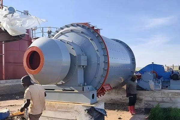
Ball mill installation checks should confirm that the civil works, mill assembly, bearings, drive train, lubrication and cooling systems, electrical equipment, instrumentation, guards and interlocks match the approved project documents before commissioning begins. The handover package should contain measured results and signed records. A visual walkaround alone is not an adequate startup release.
Start with the Approved Installation Package
The controlling documents normally include general arrangement and foundation drawings, assembly instructions, drive and coupling data, lubrication diagrams, electrical schematics, instrument lists, cause-and-effect logic, inspection records and approved changes. Confirm that the installed ball mill configuration matches the latest revisions. Red-line drawings and field changes need formal acceptance before they become part of the handover record.
Assign ownership for every check. Civil, mechanical, electrical, instrumentation, process and safety teams should sign only the systems within their competence. Record unresolved items with a responsible person, due date and startup impact instead of hiding them inside a general punch list.
Seven Ball Mill Installation Check Groups
| Check Group | Evidence Required | Why It Matters | Release Condition |
|---|---|---|---|
| Documents and changes | Current drawings, manuals, inspection records, approved deviations and punch-list status. | The team needs one verified installation basis. | Critical changes are approved and startup-blocking items are closed. |
| Foundation and support | Civil acceptance, grout record, anchor-bolt record, base condition and survey results required by the project. | The foundation establishes support and alignment stability. | The responsible engineer accepts the installed condition. |
| Mill mechanical assembly | Bearing, shell, trunnion, liner, fastener, seal, access and guard inspection records. | Incomplete assembly can create contact, leakage or personnel hazards. | Assembly matches the equipment instructions and open defects are resolved. |
| Drive alignment | Motor, coupling, gearbox, pinion and girth-gear checks applicable to the installed drive. | The connected train must transfer torque without unintended loading or contact. | Measured results meet the project-specific procedure. |
| Lubrication and cooling | Correct fluids, cleanliness, flushing where specified, valve line-up, pressure/flow tests, leak checks and instrument function. | Bearings and gearing need established lubrication before rotation. | All required auxiliaries operate and interlocks are proven. |
| Electrical and controls | Grounding, insulation reports, rotation logic, instrument calibration, emergency stops, alarms and trip tests. | The drive must start, monitor and stop in the intended sequence. | Qualified personnel sign the electrical and protection records. |
| Commissioning readiness | Risk assessment, operating procedure, communications, exclusion zones, baseline data plan and approved startup sequence. | The first run is a controlled test with defined stop criteria. | The commissioning authority approves startup. |
1. Confirm Foundation and Mechanical Completion
Verify that the foundation, soleplates or bearing bases, grout and anchors have been accepted against the project drawings and civil specification. Do not publish or borrow a generic bolt torque, grout cure time or level tolerance: these depend on the foundation design, fastener condition, lubrication state and equipment package.
Mechanical completion should cover shell and trunnion assembly, bearings, seals, liners, feed and discharge connections, inspection covers, platforms, stairs, guards and lifting provisions. Remove transport restraints only under the approved procedure. Check that tools, loose fasteners, packaging and temporary supports have been cleared before any rotation test.
2. Verify the Complete Drive Train
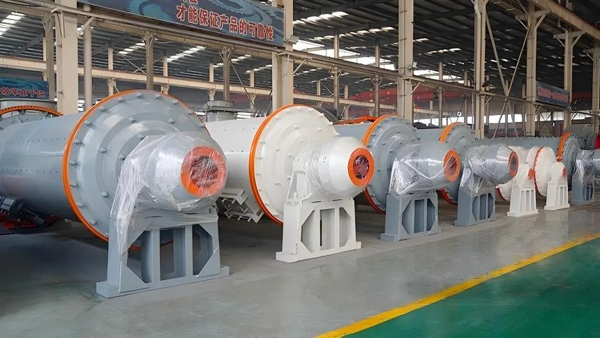
Alignment is a system check, not an isolated motor reading. Depending on the design, the train can include motor, coupling, gearbox, pinion, girth gear, inching drive and brakes. Record the alignment method, measurement locations, installed condition and acceptance criteria. Where the approved method accounts for thermal movement or foundation settlement, preserve those assumptions in the report.
Inspect fasteners, keys, coupling elements, gear guards and lubrication points. Confirm gear contact, backlash or clearances only by the supplied procedure. Before coupling or loaded rotation, the responsible team should also verify the intended direction of rotation and the availability of the approved barring or inching method.
3. Prove Lubrication, Cooling and Hydraulic Auxiliaries
Correct oil identity and cleanliness are as important as oil level. Match each lubricant to the equipment documentation, confirm storage and transfer cleanliness, and retain filling or analysis records where required. Verify pipe installation, flushing status, filter condition, valve position, cooler supply, reservoir level and leak-free connections.
Run auxiliary systems before the main drive when the equipment sequence requires it. Demonstrate pressure, flow, level and temperature instruments together with their alarms and permissives. A pump that runs locally does not prove that the main drive is protected by the intended interlock.
4. Test Electrical, Instrument and Protection Functions
Electrical completion
Qualified personnel should close grounding, cable termination, insulation, motor and drive records. Confirm phase sequence and rotation logic through the approved test method before the mill is allowed to run.
Protection completion
Test emergency stops, guards or access switches, lubrication permissives, temperature and pressure trips, local/remote selection, alarms and shutdown logic. Record the initiating device and observed response for each test.
Connected equipment also matters. Verify the start and stop relationships with feeding, discharge, classification and downstream systems. The ball mill classification circuit must prevent uncontrolled material accumulation when one component is unavailable.

5. Use a Staged Commissioning Sequence
The commissioning plan should define each stage, responsible personnel, permitted duration, measurements, communication method and stop criteria. Typical progression moves from auxiliary-system testing to controlled rotation, no-load observation and then limited process introduction. The exact order depends on the installed package and site procedure.
- lubrication pressure, flow, level and temperature at defined locations;
- bearing and drive temperatures after instruments have stabilized;
- vibration at the specified measurement positions;
- motor current, speed and direction of rotation;
- gear, coupling and bearing noise or contact observations;
- oil, water, slurry and seal leakage;
- alarm, trip and emergency-stop responses;
- time, operating condition, instrument identity and the person recording each result.
Baseline data become useful only when the operating condition and measurement position are documented. Select the vibration method and acceptance criteria for the actual machine and drive arrangement; a general vibration number is not a substitute for the correct equipment standard or manufacturer limit.
Transition from Commissioning to Stable Operation
After mechanical and no-load acceptance, introduce material according to the process plan. Confirm that feed, water and classification systems respond together. The operating team should then establish normal ranges for the installed circuit rather than expecting first-run values to represent steady production.
Use the grinding mill feed-size control record and the relevant wet grinding process data to separate installation issues from changing ore or slurry conditions. Preserve the commissioning baseline for later maintenance comparisons across the wider grinding equipment system.
Control Hazardous Energy During Checks
Commissioning alternates between isolated inspection and controlled energization, so the team must know which state applies at every moment. The official NIOSH hazardous-energy control resource guide emphasizes written procedures, identification of all energy sources, isolation verification, training and joint review before equipment returns to service. Site risk assessments and authorized procedures govern the work.
Frequently Asked Questions
What should be checked before commissioning a ball mill?
Confirm approved documents, foundation acceptance, mechanical completion, drive alignment, lubrication and cooling readiness, electrical tests, instrumentation, guards, alarms, trips, emergency stops and the staged commissioning plan. Each item needs project-specific evidence and responsible sign-off.
Can a ball mill be commissioned after a visual inspection?
No. A visual inspection cannot verify alignment, electrical integrity, lubricant condition, instrument calibration or protection logic. Commissioning release should be based on measured and signed records.
Which alignment values should be used for a ball mill drive?
Use the values and method in the approved mill, motor, coupling, gearbox and gear-drive documentation. The installed drive arrangement, measurement condition and thermal assumptions determine the applicable criteria.
What data should be recorded during the first run?
Record the operating stage, time, lubrication conditions, bearing and drive temperatures, vibration at defined points, motor current, speed, direction, leakage, abnormal noise and every alarm or trip response required by the commissioning plan.
When is a ball mill ready for process feed?
It is ready only after the commissioning authority accepts the preceding test stages, critical defects are closed, protection functions are proven and the connected feed, discharge and classification systems are available under an approved operating procedure.
For equipment documentation or configuration support, provide the verified mill duty, drive arrangement, site power, process flow and project status through the Vanore Mining contact page.